Solid Works is an awesome mechanical design tool. The toolbox it comes with is just awesome... bless the people who created it...
Ok, Im gonna slow down here...
- What is the ToolBox in solid works?
- How to use the ToolBox to design gears according to your requirement!!
SolidWorks Toolbox is a library of parts that uses "Smart Part" Technology to automatically select fasteners and assemble them in the desired sequence." well thats quoted from wikipedia... yeah my bad... now to simplify stuff...
 |
| If u cant find where Design Library is!!! Itz the first step to design a spur gear in solid works |
Click the Design Library... then click Toolbox....and expand the tree... wollah... you get access to nuts, bolts, gears.... ahh the awesomeness of Solid Works...
How to use the ToolBox to design gears according to your requirement
Now select Ansi Inch... then Power Transmissions... then Gears... then select Spur Gears... Then right click on Spur Gears.... then you get...
 |
| Click on Create Part, to get further into designing a spur gear in solid works :P |
Now you will get a screen like this... u need to get the property window to set the parameters... click on the clickable that the arrows are directing on the following image....
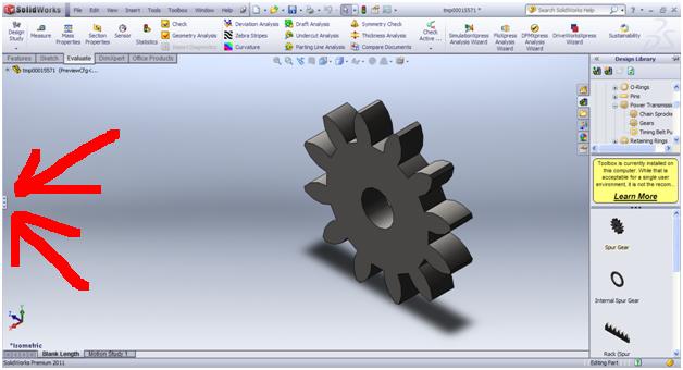
Now you will get something like...
 |
| wait whatz with all these parameters here |
NOW--- most of non mechanical engineers like me would know N and Do... so to get the required Do from the N that we already know, we need to calculate the value of p and chose that value on the property window.....
p = (N+2)/Do
and thatz the magic formula to get the desired outside diameter and teeth number for your spur gear.
Now this equation is only useful if you are using the ANSI INCH toolbox....
Now if you chose ANSI Metric toolbox and create a spar gear part from that....
the equation is a bit different... there you wont find Diametral Pitch(p) but you have to select Module(m)....
The equation for this one is m = Do/(N+0.07874)
After you set all the parameters in the Spur Gear property manager click the green arrow and Solid Works would do itz magic and draw the Spur Gear with the desired outside diameter and number of teeth... :D